|
Laboratory Tests of Electropneumatic Vibroisolation Systems
PLUTA, Janusz1, PODSIADŁO, Andrzej2 & KONIECZNY, Jarosław3
Abstract:This article presents the issue of experimental testing of mechanical vibration reducing systems, built with use of pneumatic and electropneumatic elements and sub-assemblies. Laboratory test stand built for this purpose is discussed in the first part, after brief introduction. Most important units and technical parameters of the stand are described together with its testing potential. Then we show the structure of vibroisolation systems constructed using electropneumatic, proportional and servovalve technique, which are currently tested on the stand. Selected test results for one of these systems are shown below. Purposefulness of undertaking and continuation of laboratory tests described below is justified in recapitulation. The article was supported by Polish Academy of Science (KBN) - grant No. 7T07C00916.
Keywords: vibration, isolation, control, measurement, electropneumatic
1. Introduction
In recent years we have noticed an increasing interest in the issue of mechanical vibrations, particularly in the aspect of their harmfulness. Such vibrations are often found as an disturbance accompanying operation of various machines and installations. They appear as vibrations of elements and complexes of machines and installations. For many years now scientific research has been carried out to elaborate methods and technical means supposed to neutralize effects of harmful influence of vibrations. Usage of systems designed to eliminate vibrations, referred to as vibration reducing systems or vibroisolation (vibration isolation) systems, is one of the methods of protection against negative influence of mechanical vibrations. The cheapest and most popular systems are those constructed with use of passive elements, among others including the pneumatic ones. Experiments carried out so far have proved that in many cases such systems are of little efficiency. The result of low frequency character of vibrations of many objects is a not sufficiently effective passive vibroisolation of such objects. Methods, which employ active systems of vibration control, offer wider range of options in this field [1]. Such systems contain an exterior power source, which may provide or absorb energy from any part of a machine, if only controlled in an appropriate manner. We connect to the vibroisolated object a properly controlled actuator, e.g. pneumatic, which produces energy compensating forces generating vibrations. Many concepts allowing preparation of active vibration reducing systems are known, but most of them have never been put into practice. The reason of lack of implementation is, among others, the absence of sufficient experience in this field, which may be gained only when working with real systems. One of the vital conditions for further development of active vibration reducing methods is wider than so far use of experimental research. Such research may be performed on both physical models and real systems. Nevertheless, in order to perform tests of this kind we need laboratory stands or proving grounds. Scientists employed at the Processes Control Department of the University of Mining and Metallurgy in Cracow, who understand significance of experimental research, have started, together with a simulation research, a long-term program of laboratory and proving ground research on vibroisolation systems. Major part of the testing will be carried out at a laboratory stand built specially for this purpose [2]. The research on active vibration control systems built with use of electropneumatic and electrohydraulic elements and sub-assemblies has been emphasized. Currently, electropneumatic systems are tested. Sample results of laboratory tests, carried out for one of such systems, are shown below.
2. Description of the test stand
Figure 1 shows a general diagram of the laboratory stand designed for testing mechanical vibration reducing systems. The whole stand consists of several cooperating units; some of them have been installed permanently, while others are exchangeable.
Figure 1. Diagram of the laboratory stand
Permanently installed units are:
- Carrying structure consisting of frame 1 and plate 2;
- Mechanical vibration generator unit (VG) 4;
- Hydraulic power supply;
- Compressor power pack;
- Control and measurement system.
Exchangeable elements and units of the stand are:
- Mobile platforms 6, 7;
- Tested vibration reducing system (VRS);
- Set of weights 8.
Standard aluminum sections of adequate stiffness have been used to build frame 1. Mobile platforms 5, 6, and 7, equipped with line slide bearings, are also made of such sections. Frame 1 has been fastened to heavy steel plate 2, seated on four vibroisolators 3. Electrohydraulic mechanical vibration generator (VG) 4 has been installed in the middle part of the plate. Its task is to generate platform 5 oscillatory movement characterized by suitably adjusted displacement parameters (frequency, amplitude and signal shape). Hydraulic power supply powers the generator. Elements of the tested vibration reducing system are installed between platforms 5 and 6; or 5, 6 and 7 (depending on structure). Figure 1 shows the stand as prepared for testing of one degree of freedom (1dof) systems. Platform 7 is not used during tests of such systems. Tested systems may be weighted with plates 8, mounted to appropriate platform (6 or 7). Electropneumatic vibroisolation systems are powered directly from the compressor power pack. Basic parameters of mechanical construction of the stand are as follows:
- Total weight - 1400 kg;
- Overall dimensions - 1100 ´ 1100 ´ 2800 mm.
The mechanical vibration generator unit makes an electrohydraulic system of piston position control, constructed in accordance with the servovalve technique. The unit has been made as a compact wireless structure, in order to obtain best possible dynamic properties. It consists of servomotor and mating with it controlling, measuring and protecting elements. Hydraulic elements of the unit are fastened to the common connection panel, installed directly on cylinder. Two elements, cylinder and servovalve SV, which make the whole servohydraulic system, are first of all responsible for static and dynamic properties of the hydraulic part of the generator. The remaining elements of the unit, not shown on the drawing, basically have protective and safeguarding character. Standard catalogue elements have been used for construction of the generator unit, with exception of cylinder. Hydraulic cylinder is an element of express quality. It is a device of bilateral action, with double-sided piston rod and two-way braking. A specially selected piston and pilot sleeves packing has been used and precise surface treatment of cylinder and piston rod bearing surfaces has been performed in order to minimize frictional resistance of its moving elements. Casing pipe protects lower piston rod when sliding out of cylinder. The pipe is ended with a flange making a footing of the generator, which is used to fix the whole unit in the stand. The servomotor is equipped with a rod-type, magnetostriction displacement transducer DT1, installed in casing pipe. The transducer used here is of touchless type and features high precision and operating speed. A flow servovalve for control of work of the cylinder has been installed. The servovalve is of standard type, with mechanical feedback and no overlap of the slide valve.
Basic parameters of vibration generator:
- Working pressure - 21 MPa;
- Piston speed - up to 2 m/s;
- Piston diameter - 63 mm;
- Piston rod diameter - 50 mm;
- Piston stroke - 250 mm;
- Vibration frequency - up to 85 Hz.
Multi-pump hydraulic power supply, a separate and freestanding assembly, is the source of hydraulic energy of the generator. One of the pump units of the station allows stepless adjustment of power supply flux discharge. Owing to this we may precisely adjust discharge of hydraulic feeder to current demand of the vibration generator. This unit is connected with the generator through flexible hydraulic hoses.
The compressor power pack is used when testing pneumatic, electropneumatic or pneumahydraulic vibration reducing systems. The unit consists of air-compressor, elements for compressed air preparation, and pneumatic tanks. The unit allows feeding the tested vibration reducing system with compressed air of required pressure, intensity of flow, and purity.
Basic parameters of the unit:
- rated pressure - 0,6 MPa;
- maximum pressure - 1 MPa;
- discharge - 3,8 dm3/s (at p = 1 MPa).
Weights set contains metal plates of specified weights, which may be fixed to any selected platform of the stand.
Figure 2. Diagram of control and measurement system
Diagram of control and measurement system is shown in figure 2; it is used to control work of the generator and the tested vibration reducing system, as well as to record selected physical quantities. Control of VG unit and VRS unit is performed from separate control sub-units: SU1 and SU2. First of the sub-units consists of Personal Computer I with installed control and measurement card PCL 818 HG made by Advantech, and a terminal boards type PCL 8115. Second of the sub-units consists of Personal Computer II, control and measurement computer dSPACE, and specially designed terminal boards. Sets of pressure, displacement and acceleration measurement transducers are connected to both sub-units. Sub-unit SU1 has been employed to control work of the vibration generator. Programming of Personal Computer I, which controls outputs and inputs of measurement card PCL 818 HG, is carried out with the Matlab/Simulink graphic editor equipped with two sets of toolbox: RTW (Real Time Workshop) and RTWT (Real Time Windows Target). RTWT allows to set going the C code generated by RTW on Personal Computer. Computer using Windows 95/98 operating system becomes a real-time controller. Control algorithm bases on PD controller, which stabilizes displacement of vibration inductor piston rod. Next to control, the card allows registration of signals (up to sixteen), received from measurement transducers. The other sub-unit is employed to control vibration reducing system. In this sub-unit the dSPACE computer (working as a controller) is programmed by Personal Computer II through Ethernet. Using of floating-point signal processor TMS320C31, manufactured by Texas Instruments, allows generating control algorithms, which are complicated from the point of view of performing calculations. Processor programming is performed through use of a source code created in the Matlab/Simulink set. Virtual control desk allowing modifications of the system condition variables in real time has been created in the COCKPIT program. On the other hand TRACE program allows visualizing measured and converted signals. Sets of transducers used in the control and measurement system consist of:
- Piezoelectric pressure transducers, type MBS32, manufactured by Danfoss;
- Magnetostriction transducers of displacement, type BTL-2, manufactured by Balluff;
- Acceleration transducers, type ADXL05 and ADXL50, manufactured by Analog Devices.
3. Testing potential of the stand
The demonstrated stand has been designed first of all for testing of fluid and electro-fluid vibration reducing systems, although other systems are not excluded. Its basic advantage is universality, resulting from properties of units used for construction of the stand.
Figure 3. Examples of mechanical models of vibration reducing systems for testing at the stand: mp, ms - load masses; bs, bp - viscosity friction coefficients; ks, kp - stiffness coefficients; xw, xs, xp - displacement; Uw - vibration generator; Us - active element
As a result we obtain wide testing potential of the stand, among others allowing to:
- test vibroisolation systems of varying mechanical structure and varying physical character, e.g. pneumatic, electropneumatic, airdraulic, electrohydraulic, etc.;
- quickly determine vibroisolators quality indicators, e.g. factor of displacement transmissibility;
- select input parameters, such as:
- signal shape (e.g. sinusoidal, rectangular, random), amplitude, frequency, power output;
- test various control algorithms in case of active vibration reducing systems;
- easily modify the structure of the tested system;
- easily assemble and disassemble the tested system in the stand.
Diagrams of samples of mechanical models of selected vibration reducing systems, which may be put for testing at the described stand, are shown in figure 3.
4. Samples of tested vibration reducing systems
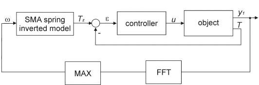
Within the framework of the testing program prepared for vibration reducing systems, a group of active systems basing on electropneumatic, proportional and servovalve technique has been selected. Basic pneumatic elements of such systems are the actuator, and proportional valve or servovalve. We may refer to systems constructed on the basis of such elements, as the servopneumatic systems. Proportional valves and servovalves used in such systems have been constructed in order to allow very precise control of pneumatic drive units, with use of weakest possible electric input signals. The term servopneumatic systems means not only particular elements of the pneumatic system, but first of all cooperation of the applied control technique, pneumatic drive for transporting energy, and electronics used for data conversion. In connection with the above, active mechanical vibration reducing systems basing on servopneumatic systems require from designers, contractors and researchers knowledge of the whole range of technology areas, in particular: pneumatic drive and control, technique of regulation, electronics, measurement techniques.
|
Figure 4. System controlled by proportional pressure regulating valve |
Figure 5. System controlled by flow servovalve 5/3 |
The tested systems will be constructed with use of bellow, bag, membrane, and piston cylinders with low-friction packing. The following electropneumatic elements are expected to control directly these cylinders:
- proportional pressure regulating valve,
- reduction pressure servovalve,
- flow servovalves 5/3 and 3/3.
Figure 6. System controlled by two flow servovalves 3/3
The described drive and control units allow constructing various structures. Three sample electropneumatic vibroisolation systems are shown on diagrams 4, 5, and 6. Each of mentioned systems consists of pneumatic cylinder 1, electropneumatic valve 2 (or system of valves), air tank 3, electronic control system 4 and measurement transducers 5 (of displacement), 6 and 7 (of pressure). Proper selection of cylinders and proportional valves or servovalves for such systems has essential influence on their static and dynamic properties. Moreover, these properties are influenced by: manner of electrical controlling carried out by electromechanical converter of proportional valve or servovalve, measurement line appearing in feedback, as well as control algorithm applied to a particular vibration reducing system.
5. Test results of a selected vibroisolation system
Laboratory testing of electropneumatic vibroisolation systems, among others, aims to:
- determine parameters and static and dynamic characteristic features of pneumatic and electropneumatic components of the system, if manufacturer does not show such information in his catalogue,
- determine range of variation of factor of displacement transmissibility,
- determine amplitude-frequency and phase-frequency characteristics,
- test control algorithms in case of active systems,
- determine multipliers necessary for mathematical modeling of vibration reducing systems,
- verify simulation test results performed on mathematical models of vibroisolation systems.
Selected results of laboratory tests, demonstrated in figures 7 and 11, concern the vibration reducing system shown on diagram 4. This system consists of double convolution ballows cylinder 1 with 85-mm stroke, and proportional pressure regulating valve 2. Control valve used here is equipped with an integrated electronic control system. The system described above (VRS) has been installed in the stand between platforms 5 and 6 in a manner shown in figure 1. During performance of tests platform 6, including added weight plates 8, weighed 230 kg.
Figure 7. Static characteristic of double convolution bellows cylinder
Experimentally determined static characteristic of double convolution bellows cylinder is shown in figure 7. This characteristic shows relation between height of the cylinder and pressure of air filling it, determined for increasing and decreasing pressure. It has a hysteresis, the maximum value of which (about 16 mm) appears in the lower range of pressure values. According to the recommendation of the cylinder manufacturer, value of hysteresis for set load of 230 kg, at pressure of 0,335 MPa, should be 6 mm.
Figure 8. Time courses of changes of cylinder height and pressure in its chamber
Further tests have been performed for vibroisolation system with stabilized pressure in the cylinder chamber. The researchers applied to the tested system an input function of sinusoidal signal with steplessly changing frequency, similar to free vibration frequency of the tested system (about 2,75 Hz). Such input function, appearing as displacement of +/- 5-mm amplitude, was generated by vibration generator, interacting with bottom plane of the cylinder through platform 5. Figure 8 shows time courses of changes of bellows cylinder height and pressure of air filling it, resulting from change of volume. Value of pressure in the cylinder chamber was changing throughout the test by about +/- 7%, as compared to the set value of 0,35 MPa. Simultaneously the cylinder height was changing by about +/- 17 mm, to reach the maximum value of 175 mm. Maximum allowed height of this cylinder is 180 mm.
Figure 9. Step response of pressure valve
Figure 9 demonstrates step response of control valve 2, determined as an output pressure. Delay time of this valve is 0,03 s, and its time-constant is 0,045 s. Diagram shown was determined at 50% of the nominal control signal value, which responds to the value of pressure on valve output equal to 0,3 MPa.
Figure 10. Factor of displacement transmissibility
Figure 10 shows course of changes of an essential for vibroisolation systems value, that is factor of displacement transmissibility T (defined as quotient of amplitudes of vibroisolated mass displacements and an input function system). This coefficient has been determined as a function of pressure of air in the cylinder chamber and frequency of input signal vibrations. Due to limitations connected with parameters of the employed cylinder, the tests were performed for pressures from within the range of 0,25 ¸ 0,35 MPa. When out of this range, cylinder height exceeds allowed values (minimum and maximum). From the received diagram, we may imply that at set load the free vibration frequency of the tested system very insignificantly depends on pressure in the cylinder, and when height increases, frequency decreases. Nevertheless, even slight increase of pressure results in significant increase of resonance peak (excedance), which is a serious defect in case of active vibroisolation systems. From the point of view of vibration theory, kinematic structure of the tested system stays in accordance with that shown on figure 3a (at stabilized pressure in cylinder chamber). Theoretical vibroisolation condition (T<1) for such system is represented by inequality: f/f0>21/2. Symbols f and f0 mark respectively an input function frequency and the free vibration frequency. Due to input function frequency fluctuations, and in order to ensure appropriately small factor of displacement transmissibility, we accept practical area of vibroisolation determined by the inequality: f/f0>3 [1], instead of the theoretical area described above. Therefore, vibroisolation of tested mass is effective only for values exceeding 8 Hz.
Figure 11. Bode frequency response at pressure of 0,3 MPa
Figure 11 shows amplitude-frequency and phase-frequency characteristics (Bodes charts) for the tested vibration reducing system, determined on the basis of recorded displacements of platforms 5 and 6 (fig. 1). These characteristics were determined at air pressure of 0,3 MPa in the cylinder chamber. We may read from amplitude-frequency characteristic, that at frequency of 9 Hz vibration damping is 20 dB. It means that the tested system caused ten-fold reduction of vibration amplitude.
6. Conclusions
The laboratory stand presented in this article allows fast performance of testing elements and pneumatic (electropneumatic) units used in vibration reducing systems. Two independent control and measurement sub-units basing on dSPACE and PCL-818HG cards and software cooperating with them, has been installed in the stand and it proves to be very efficient. Separate trajectory of vibration generator with unchanging structure and the trajectory of vibration reducing system, structure of which can be modified in the aspect of employed vibroisolation system and applied control algorithm, indicate universality and high testing potential of the stand. Additional advantage is an option of fast change of configuration of used measuring transducer; this allows measurments of physical values searched for at the particular moment. Experience so far, gained during laboratory and simulation tests of electropneumatic vibration reducing systems, indicate purposefulness of undertaking and further continuation of such research. Such tests are justified, among others, by the fact that in most cases there is a shortage of technical parameters necessary for both: simulation tests and designing of active vibroisolation systems. Selected test results, demonstrated on the example of one of vibration reducing systems, have proved its considerable limitations resulting from properties of employed elements (bellows cylinder and proportional pressure regulating valve). Due to lack of appropriate technical data, only at the stage of laboratory tests it became possible to prove whether the tested system could be effectively used in an active vibration reducing system. When comparing manufacturers' catalogues and folders of electropneumatic proportional valves and servovalves, we may notice that some of them avoid showing construction details, parameters and characteristics describing dynamic properties of the offered elements. In such situation potential possibilities of mathematical modeling of systems basing on such elements are highly limited. This is why one of the objectves of further laboratory tests is going to be determination of experimental mathematical models of active vibroisolation systems, which include influence of controlling and interfering signal (from vibration generator) on dynamic properties of these systems. Test results obtained on such models allow evaluation of usability of the analyzed vibration reducing systems as active systems.
Streszczenie: Artykuł przedstawia problematykę eksperymentalnego wyznaczania podstawo-wych parametrów oraz charakterystyk elektropneumatycznych układów redukcji drgań mechanicznych na przykładzie układu zbudowanego z siłownika dwufał-dowego oraz proporcjonalnego regulatora ciśnienia. W części pierwszej opisano zastosowane do badania stanowisko laboratoryjne oraz badany układ redukcji drgań. W drugiej części zaprezentowano wyniki przeprowadzonych badań.
Słowa kluczowe: aktywne układy redukcji drgań mechanicznych, badania laborato-ryjne, układy elektropneumatyczne.
References
[1] KOWAL, J., 1996 Sterowanie drganiami. Gutenberg Krakow. ISBN 83-86310-06-5
[2] KONIECZNY, J., ORNACKI, R., PLUTA, J., 1999. Stanowisko do badan sterowanych ukladow redukcji drgan. IV Szkola Metody Aktywne Redukcji Drgan i Halasu. Krakow-Krynica 1999. ISBN 83-86310-08-1 |